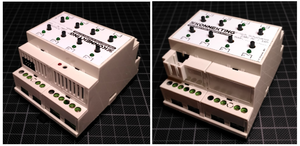
DFF4.1
| DFF4.1 | |
|---|---|
| Developer | Alexander Christian |
| Status | Version 1.0 finished |
| Microcontroller/Board | M0dularisM+ |
| KNX connectivity | Siemens BCU, Eugen's µBCU |
Description
The purpose of this actuator is, to control Roto Rototronic skylight with shutters and/or sun blinds. It has 4 "channels". Each channel internally uses two relays: One for the open-action, and one for the close-action.
Of course you can also control your Roto Rototronic skylight with help of a standard switch-actuator. But then you don't have the possibility to "open the window 75%" or "close the shutter 80%". The firmware for DFF4.1 provides all this neat feature that you know from typical shutter/blinds actuators.
Hardware
This actuator consists of the following REG parts:
- M0dularis+
- 8x Button + 8x LED
- 8x Relay Bistable, bus powered (8 relays in total, 2 for each channel = 4 channels).
I2C address on application board:
A0: 1
A1: 0
A2: 0
I2C address on frontend board:
A0: 0
A1: 0
A2: 0
Software
User Documentation
Check here for the DFF4.1 User Manual
Developer Documentation
Firmware sourcecode is on github: https://github.com/KONNEKTING/DFF4.1 Follow this guide for updating the firmare from source-code: KONNEKTING USB Firmware Update
Get a DIY kit
You are interested in this actuator? Great! This device is available as a DIY kit.
The kit includes all required parts with pre-soldered SMD parts and pre-flashed controller board.
You only need:
- soldering iron and solder
- a screw driver
- a sharp knife with a fine tip
- a working KNX installation where you can connect the device to
- ~2-3hrs to build it according to the build instructions linked on this page
- a computer: Windows, Linux or MAC that is able to run KONNEKTING Suite plus a KNX IP Interface or an KNX IP Router.
- for updating the firmware: A Mini USB cable (Not Micro-USB like on your smartphone. Mini USB is a big thicker as Micro USB)
Please write a mail to info@konnekting.de and refer to this page.
Build It
This actuator uses three PCBs, a bunch of SMD components as well as a lot of mechanical parts. As most users are not able to solder SMD, the PCBs are pre-soldered with all SMD components. Due to the big amount of parts, this actuator comes as a DIY kit: You have to solder non-SMD parts yourself and build up the device and finally flash the firmware with help of a USB connection.
Check here for the DFF4.1 Building Instructions
Help
If relays do not work as expected, you can run this test-sketch to be able to switch relais by serial console. Commands follow this syntax (\n = LF/LineFeed/NewLine):
[a-h0-1]\n
f.i. "a0" disables relay A, "f1" enables relay F On startup all relays are disabled. It is recommended to use this test without attached window/shutter, but with am multimeter/continuity-tester to be able to test relay by relay.
  1#include <Wire.h>
  2#include <Adafruit_MCP23017.h>
  3
  4Adafruit_MCP23017 mcp;
  5#define LED A5
  6#define EN A0
  7
  8// MCP23017 Output register<->pin map
  9#define OA0 0
 10#define OA1 1
 11#define OA2 2
 12#define OA3 3
 13#define OA4 4
 14#define OA5 5
 15#define OA6 6
 16#define OA7 7
 17#define OB0 8
 18#define OB1 9
 19#define OB2 10
 20#define OB3 11
 21#define OB4 12
 22#define OB5 13
 23#define OB6 14
 24#define OB7 15
 25
 26
 27#define A_SET   OB1
 28#define A_RESET OB0
 29
 30#define B_SET   OB3
 31#define B_RESET OB2
 32
 33#define C_SET   OB5
 34#define C_RESET OB4
 35
 36#define D_SET   OB7
 37#define D_RESET OB6
 38
 39#define E_SET   OA0
 40#define E_RESET OA1
 41
 42#define F_SET   OA2
 43#define F_RESET OA3
 44
 45#define G_SET   OA4
 46#define G_RESET OA5
 47
 48#define H_SET   OA6
 49#define H_RESET OA7
 50
 51void setup() {
 52
 53  SerialUSB.begin(115200);
 54
 55  SerialUSB.println("SetupMCP Relais Test ...");
 56
 57  pinMode(LED, OUTPUT);
 58  pinMode(EN, OUTPUT);
 59  digitalWrite(LED, HIGH);
 60  digitalWrite(EN, HIGH);
 61
 62
 63  mcp.begin(1);
 64
 65  for (int i = 0; i < 16; i++) {
 66    mcp.pinMode(i, OUTPUT);
 67  }
 68
 69  pulseMCP(A_RESET);
 70  pulseMCP(B_RESET);
 71  pulseMCP(C_RESET);
 72  pulseMCP(D_RESET);
 73  pulseMCP(E_RESET);
 74  pulseMCP(F_RESET);
 75  pulseMCP(G_RESET);
 76  pulseMCP(H_RESET);
 77
 78
 79  SerialUSB.println("... done");
 80
 81  // initial delay
 82  delay(1000);
 83  SerialUSB.println("Initial delay done.");
 84  SerialUSB.println("Waiting for command...[a-h0-1]");
 85}
 86
 87//84
 88#define WAIT_TIME 84
 89
 90//16
 91#define SET_TIME 16
 92
 93String cmd;
 94
 95void loop() {
 96
 97  cmd = SerialUSB.readStringUntil('\n');
 98
 99  if (cmd.length() > 0) {
100    SerialUSB.print("Command: ");
101    SerialUSB.println(cmd);
102
103    if (cmd == "a1") {
104      pulseMCP(A_SET);
105    } else if (cmd == "a0") {
106      pulseMCP(A_RESET);
107    }
108
109    else if (cmd == "b1") {
110      pulseMCP(B_SET);
111    } else if (cmd == "b0") {
112      pulseMCP(B_RESET);
113    }
114
115    else if (cmd == "c1") {
116      pulseMCP(C_SET);
117    } else if (cmd == "c0") {
118      pulseMCP(C_RESET);
119    }
120
121    else if (cmd == "d1") {
122      pulseMCP(D_SET);
123    } else if (cmd == "d0") {
124      pulseMCP(D_RESET);
125    }
126
127    else if (cmd == "e1") {
128      pulseMCP(E_SET);
129    } else if (cmd == "e0") {
130      pulseMCP(E_RESET);
131    }
132
133    else if (cmd == "f1") {
134      pulseMCP(F_SET);
135    } else if (cmd == "f0") {
136      pulseMCP(F_RESET);
137    }
138
139    else if (cmd == "g1") {
140      pulseMCP(G_SET);
141    } else if (cmd == "g0") {
142      pulseMCP(G_RESET);
143    }
144
145    else if (cmd == "h1") {
146      pulseMCP(H_SET);
147    } else if (cmd == "h0") {
148      pulseMCP(H_RESET);
149    }
150
151    SerialUSB.println("\n\nWaiting for command...[a-h0-1]");
152  }
153
154}
155
156void pulseMCP(int i) {
157  SerialUSB.print("Pulse at addr #");
158  SerialUSB.print(i);
159
160  mcp.digitalWrite(i, HIGH);
161  delay(SET_TIME);
162  mcp.digitalWrite(i, LOW);
163  delay(WAIT_TIME);
164  SerialUSB.println(" *DONE*");
165}
