Difference between revisions of "DFF4.1 Building Instructions"
Konnekting (talk | contribs) |
Konnekting (talk | contribs) |
||
| (13 intermediate revisions by the same user not shown) | |||
| Line 34: | Line 34: | ||
|- | |- | ||
|8 | |8 | ||
| − | |tactile push button, | + | |tactile push button, 9.5mm/13mm, "Frontend Buttons" |
|- | |- | ||
|1 | |1 | ||
| − | |tactile push button, | + | |tactile push button, 12.5mm/16mm, "Programming Button" |
|- | |- | ||
|1 | |1 | ||
| Line 71: | Line 71: | ||
|- | |- | ||
|1 | |1 | ||
| − | |pcs of | + | |pcs of ribbon cable, ~10cm length |
|- | |- | ||
|1 | |1 | ||
| Line 94: | Line 94: | ||
Take the 2x4 and 2x8 and both 2x3 micromatch connector (which are not shown, but need to be modified as well) and cut a bit of the orientation pin as shown: | Take the 2x4 and 2x8 and both 2x3 micromatch connector (which are not shown, but need to be modified as well) and cut a bit of the orientation pin as shown: | ||
| − | [[File:DFF4. | + | [[File:DFF4.1 Building Instruction cutmicromatchorientationpin.png|600px]] |
This is required, as the PCB is unfortunately missing the matching hole for this orientation pin. | This is required, as the PCB is unfortunately missing the matching hole for this orientation pin. | ||
| Line 110: | Line 110: | ||
The result shoud look like this: | The result shoud look like this: | ||
| − | [[File:DFF4. | + | [[File:DFF4.1 Building Instruction cutribboncable.png|600px]] |
| − | Carefully put the micromatch connector (2x3 for 6-wire and 2x4 + 2x8 for the 8-wire) onto the ribbon cable and crimp the connector with help of a pliers. Be really careful and take your time. Otherwise you risk damage of micromatch plug! | + | Carefully put the micromatch connector (2x3 for 6-wire and 2x4 + 2x8 for the 8-wire) onto the ribbon cable and crimp the connector with help of a pliers. |
| + | |||
| + | [[File:DFF4.1 Building Instruction micromatchcrimp.png|600px]] | ||
| + | |||
| + | Be really careful and take your time. Ensure that you crimp both micromatch parts as parallel as possible. And don't put too much pressure on the plastic. Otherwise you risk damage of micromatch plug! | ||
Ensure that you put the red-wire to the side of the orientation-pin of micromatch connector and that you put one of the 2x3 connectors with face down as shown. | Ensure that you put the red-wire to the side of the orientation-pin of micromatch connector and that you put one of the 2x3 connectors with face down as shown. | ||
| − | [[File:DFF4. | + | [[File:DFF4.1 Building Instruction assembledmicromatch.png|600px]] |
'''When soldering the sockets, LEDs or switches, ...: Start with soldering just one pin. Then check the alignment. If realignment is needed, re-heat the the pin and realign. If alignment is okay, solder the remaining pins. Fixing a wrong alignment afterwards is tricky and you might ruin the PCB. So do it first time right and check alignment twice.''' | '''When soldering the sockets, LEDs or switches, ...: Start with soldering just one pin. Then check the alignment. If realignment is needed, re-heat the the pin and realign. If alignment is okay, solder the remaining pins. Fixing a wrong alignment afterwards is tricky and you might ruin the PCB. So do it first time right and check alignment twice.''' | ||
| Line 125: | Line 129: | ||
= Controller = | = Controller = | ||
| − | Close solder jumpers as shown here. Some of them might have been already closed for first production test.If so, ensure the jumpers are closed as shown. | + | Close solder jumpers as shown here. Some of them might have been already closed for first production test. If so, ensure the jumpers are closed as shown. |
| − | D10/A2 | + | |
| + | VCC TOP: | ||
| + | |||
| + | 5V | ||
| + | |||
| + | VCC BOT: | ||
| + | |||
| + | 5V | ||
| + | |||
| + | D12/A0: | ||
| + | |||
| + | A0 | ||
| + | |||
| + | D10/A2: | ||
| + | |||
| + | leave unset | ||
| − | I2C EEPROM | + | I2C EEPROM: |
A0: 0 | A0: 0 | ||
| Line 134: | Line 153: | ||
A2: 0 | A2: 0 | ||
| − | [[File:DFF4. | + | [[File:DFF4.1 Building Instruction sjcontroller.png|600px]] |
Put in micromatch sockets and solder them. Check the right orientation according to the picture here: | Put in micromatch sockets and solder them. Check the right orientation according to the picture here: | ||
| − | [[File:DFF4. | + | [[File:DFF4.1 Building Instruction micromatchsocket.png|600px]] |
| + | |||
| + | Put the MicroBCu in place and solder it from the bottom of the PCB: | ||
| + | |||
| + | [[File:DFF4.1 Building Instruction microbcu.png|600px]] | ||
Put in MiniUSB socket and solder the pins. Ensure that the two outer shielding pins have good contact and enough solder. | Put in MiniUSB socket and solder the pins. Ensure that the two outer shielding pins have good contact and enough solder. | ||
| Line 146: | Line 169: | ||
'''Check the polarity twice! Unsoldering the LED might kill the trough-hole-contact and your PCB is trash!''' | '''Check the polarity twice! Unsoldering the LED might kill the trough-hole-contact and your PCB is trash!''' | ||
| − | [[File:DFF4. | + | [[File:DFF4.1 Building Instruction LedAndButton.png|600px]] |
Put in the KNX pins and solder them. | Put in the KNX pins and solder them. | ||
| − | [[File:DFF4. | + | [[File:DFF4.1 Building Instruction knxpins.png|600px]] |
= Frontend = | = Frontend = | ||
| − | + | Search the parts you need for the frontend: | |
| + | |||
| + | [[File:DFF4.1 Building Instruction frontendparts.png|600px]] | ||
| + | |||
| + | Check the LED polarity. you will have to put in the LED as shown: The long leg with the "tiny part" in the LED is "+", the short leg with the "big part" in the LED is "-" (the other hole on the PCB): | ||
| + | |||
| + | [[File:DFF4.1 Building Instruction frontendledorientation.png|600px]] | ||
| + | |||
| + | Use the spacer to get the right distance between PCB and LED. You may need to push in the LED quite hard to get a flat sitting LED and spacer. it should finally look like this: | ||
| − | + | [[File:DFF4.1 Building Instruction frontendledalignment.png|600px]] | |
| − | + | After soldering, cut the LED legs as shown (cut all of them of course ;-) ): | |
| − | Ensure that solder-jumpers for I2C adress is correctly set to: | + | [[File:DFF4.1 Building Instruction frontendcutledpins.png|600px]] |
| + | |||
| + | Next you put in the micromatch on the bottom of the PCB like this. If you got a micromatch socket which has the shown gap only on one side, ensure you out it in like shown: | ||
| + | |||
| + | [[File:DFF4.1 Building Instruction frontendmicromatch.png|600px]] | ||
| + | |||
| + | Set the I2C address as shown by putting some solder on the pads. Ensure that solder-jumpers for I2C adress is correctly set to: | ||
A0: 0 | A0: 0 | ||
| Line 166: | Line 203: | ||
A2: 0 | A2: 0 | ||
| − | + | [[File:DFF4.1 Building Instruction frontendi2caddress.png|600px]] | |
| + | |||
| + | Finally put in the buttons and solder them. Ensure that they are sitting totally flat on the PCB: | ||
| + | |||
| + | [[File:DFF4.1 Building Instruction frontendbuttonsalignment.png|600px]] | ||
| + | |||
| + | If, after soldering, you have a lot of ugly flux on the PCB like this: | ||
| + | |||
| + | [[File:DFF4.1 Building Instruction frontendflux.png|600px]] | ||
| + | |||
| + | ... use some flux cleaner (f.i. plenty of Isopropanol. You get this on [https://www.amazon.de/Isopropanol-Isopropylalkohol-Klar-99-1000/dp/B00JXK92YI/ref=sr_1_4?ie=UTF8&qid=1525194236&sr=8-4&keywords=isopropanol Amazon]) and an old toothbrush to clean it. Finally it will look like this: | ||
| + | |||
| + | [[File:DFF4.1 Building Instruction frontendfluxremoved.png|600px]] | ||
= Application = | = Application = | ||
| − | + | Search all the application PCB required parts, like shown here: | |
| + | |||
| + | [[File:DFF4.1 Building Instruction applicationparts.png|600px]] | ||
| + | |||
| + | Close the solder jumpers and put in the 2x4 micromatch socket as shown here: | ||
A0: 1 | A0: 1 | ||
| Line 176: | Line 229: | ||
A2: 0 | A2: 0 | ||
| − | + | [[File:DFF4.1 Building Instruction applicationi2caddress.png|600px]] | |
| + | |||
| + | Flip the PCB and solder the micromatch socket. | ||
| − | + | Next step is to add the screwterminals. Try to align the terminals to the outer PCB line and finally and solder them: | |
| − | + | [[File:DFF4.1 Building Instruction applicationsolderedterminals.png|600px]] | |
| − | + | Now we go over to the relays. Put them in place, flip the PCB and solder then: | |
| − | + | [[File:DFF4.1 Building Instruction applicationrelays.png|600px]] | |
| − | + | Try to keep a minimum space between the relays as shown in the image, so that the relays do not touch each other. This is to keep the mechanical stress/vibration of one relay separated from others. | |
| + | You can use a credit card or similar as a kind of separator while soldering. | ||
| + | = Mechanical = | ||
| + | == Connecting PCBs == | ||
| − | = | + | Now that you're done with soldering, you can start to assemble all the parts. You need the following parts for this: |
| + | |||
| + | [[File:DFF4.1 Building Instruction assemblyparts.png|600px]] | ||
| + | |||
| + | First, take two screws and screw both 18mm hex-spacer to the application PCB as shown: | ||
| + | |||
| + | [[File:DFF4.1 Building Instruction assemblybottom.png|600px]] | ||
| + | |||
| + | Then take the application-to-controller cable and plug it into the socket on the application PCB: | ||
| + | |||
| + | [[File:DFF4.1 Building Instruction assemblyapplicationcable.png|600px]] | ||
| + | |||
| + | Then take the controller PCB and screw it with help of the 15mm hex-spacer on the application PCBs hex-spacer. Finally connect the cable as shown to the controller PCB. | ||
| + | |||
| + | [[File:DFF4.1 Building Instruction assemblycontroller.png|600px]] | ||
| + | |||
| + | Now it is time to connect the frontend PCB with the 2x3 micromatch cable. Plug the connector into the socket as shown here: | ||
| + | |||
| + | [[File:DFF4.1 Building Instruction assemblyfrontendcable.png|600px]] | ||
| + | |||
| + | Finally screw the frontend PCB with the remaining two screws on the hex-spacers of the controller PCB: | ||
| + | |||
| + | [[File:DFF4.1 Building Instruction assemblycomplete.png|600px]] | ||
| + | |||
| + | You're done and screw-connectiond and cables should look like this: | ||
| + | |||
| + | [[File:DFF4.1 Building Instruction assemblycompletedetail.png|600px]] | ||
| + | |||
| + | == DIN Rail case == | ||
| + | |||
| + | Unpack the case and break out the holes on the terminal covers as shown here: | ||
| + | |||
| + | [[File:DFF4.1 Building Instruction assemblycasecutouts1.png|600px]] | ||
| + | [[File:DFF4.1 Building Instruction assemblycasecutouts2.png|600px]] | ||
| + | |||
| + | I recommend using a really sharp knife like a scalpel to cutout the screw-holes. Be careful to not cut too much or break the plastik. The plastik is very soft. | ||
| + | |||
| + | If not already in place, put the plastik cover into the case: | ||
| + | |||
| + | [[File:DFF4.1 Building Instruction assemblycasecover1.png|600px]] | ||
| + | |||
| + | Then put in the cover PCB (it should held itself in place): | ||
| + | |||
| + | [[File:DFF4.1 Building Instruction assemblycasecover2.png|600px]] | ||
| + | |||
| + | Take a marker pen and mark the holes on the plastic cover as shown: | ||
| + | |||
| + | [[https://wiki.konnekting.de/index.php/File:DFF4.1_Building_Instruction_assemblycasecover3.png|600px]] | ||
| + | |||
| + | Remove the cover PCB. Your markings should look like this: | ||
| + | |||
| + | [[File:DFF4.1 Building Instruction assemblycasecover4.png|600px]] | ||
| + | |||
| + | Remove the plastic cover and drill holes on your markings. You shold take a drill that is 2-3mm thicker as the required hole size. | ||
| + | Having the drilled holes bigger that the holes in the cover PCB makes it easier for you with centering the drill and also when later on inserting the buttons and LEDs. | ||
| + | |||
| + | [[File:DFF4.1 Building Instruction assemblycasecover5.png|600px]] | ||
| + | |||
| + | [[File:DFF4.1 Building Instruction assemblycasecover6.png|600px]] | ||
| + | |||
| + | I prefer to have the DIN-rail-unlock on the top of the device. If you want the same, ensure that unlock is on the side where the USB connector is. Otherwise take the other side. | ||
| + | |||
| + | [[File:DFF4.1 Building Instruction assemblycase1.png|600px]] | ||
| + | |||
| + | Finally carefully slide the case over. You might need to swap all the terminal covers on the case by 180°: The case does only fit in one direction in the bottom part, as the notches on both sides have different sizes. Now you're done. | ||
| + | |||
| + | [[File:DFF4.1 Building Instruction assemblycase2.png|600px]] | ||
Latest revision as of 05:46, 17 May 2018
Preparation
Check that all parts are there:
| Pcs. | Part |
|---|---|
| 2 | M3 hex-spacer, nylon, 15mm, with M3 screw on one end and inner thread on other end. |
| 2 | M3 hex-spacer, nylon, 18mm, with inner threads on both ends |
| 4 | M3 screw, nylon |
| 8 | relay |
| 8 | screw terminals, cage |
| 8 | 3mm LED, green |
| 8 | 3mm LED spacer, 5mm height |
| 1 | 3mm LED, red |
| 8 | tactile push button, 9.5mm/13mm, "Frontend Buttons" |
| 1 | tactile push button, 12.5mm/16mm, "Programming Button" |
| 1 | DIN Rail enclosure, consisting of:
|
| 1 | MiniUSB socket, vertical |
| 2 | micromatch socket, 2x3 pin |
| 1 | micromatch socket, 2x8 pin |
| 1 | micromatch socket, 2x4 pin |
| 2 | micromatch plug, 2x3 pin |
| 1 | micromatch plug, 2x8 pin |
| 1 | micromatch plug, 2x4 pin |
| 1 | pcs of ribbon cable, ~10cm length |
| 1 | PCB enclosure cover, printed and drilled |
| 1 | M0dularis+ controller PCB |
| 1 | Frontend PCB, 8 Buttons, 8 LEDs |
| 1 | Application PCB, 8x BiRelay |
| 1 | MicroBCU with pinheaders |
| 2 | pins for KNX connection |
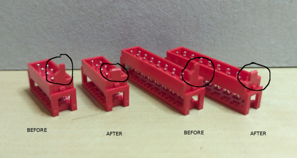
Take the 2x4 and 2x8 and both 2x3 micromatch connector (which are not shown, but need to be modified as well) and cut a bit of the orientation pin as shown:
This is required, as the PCB is unfortunately missing the matching hole for this orientation pin.
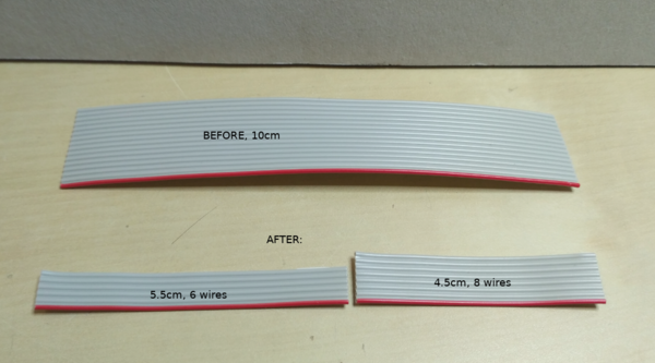
Take the 10cm ribboncable and cut the following lengths:
- 5.5cm
- 4.5cm
then
- take the 5.5cm part and reduce the wirecount to 6 wires, incl. one red wire
- take the 4.5cm part and reduce the wirecount to 8 wires, incl. one red wire
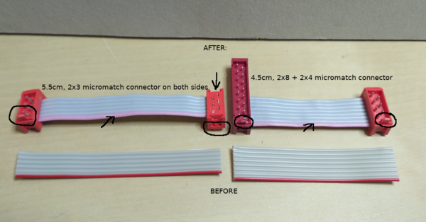
The result shoud look like this:
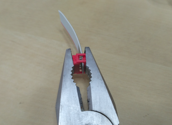
Carefully put the micromatch connector (2x3 for 6-wire and 2x4 + 2x8 for the 8-wire) onto the ribbon cable and crimp the connector with help of a pliers.
Be really careful and take your time. Ensure that you crimp both micromatch parts as parallel as possible. And don't put too much pressure on the plastic. Otherwise you risk damage of micromatch plug! Ensure that you put the red-wire to the side of the orientation-pin of micromatch connector and that you put one of the 2x3 connectors with face down as shown.
When soldering the sockets, LEDs or switches, ...: Start with soldering just one pin. Then check the alignment. If realignment is needed, re-heat the the pin and realign. If alignment is okay, solder the remaining pins. Fixing a wrong alignment afterwards is tricky and you might ruin the PCB. So do it first time right and check alignment twice.
When soldering LEDs check the polarity twice. Unsoldering "through-hole" pins can ruin the through-hole-contact and thus the whole PCB. So be careful.
It's recommended that you stick to the here described order of adding parts to the PCB. That will ease the whole process for you
Controller
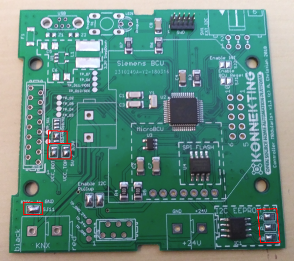
Close solder jumpers as shown here. Some of them might have been already closed for first production test. If so, ensure the jumpers are closed as shown.
VCC TOP:
5V
VCC BOT:
5V
D12/A0:
A0
D10/A2:
leave unset
I2C EEPROM:
A0: 0
A1: 0
A2: 0
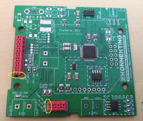
Put in micromatch sockets and solder them. Check the right orientation according to the picture here:
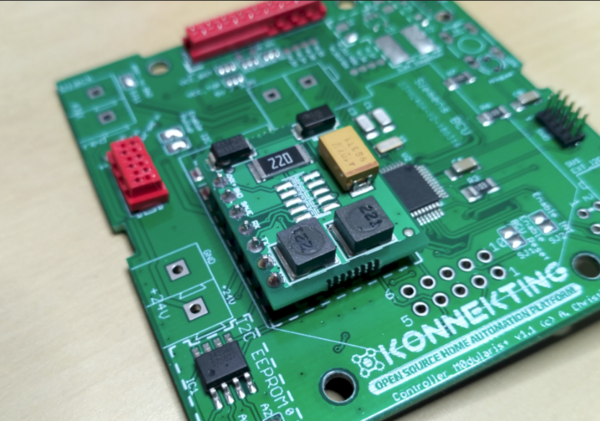
Put the MicroBCu in place and solder it from the bottom of the PCB:
Put in MiniUSB socket and solder the pins. Ensure that the two outer shielding pins have good contact and enough solder.
Put in the programming button and the LED as shown and solder them as well. Tip: It's easier to adjust the height of the LED when just soldering one pin an adjust heigth while re-heating the pin. Then check alignment and solder second pin.
Check the polarity twice! Unsoldering the LED might kill the trough-hole-contact and your PCB is trash!
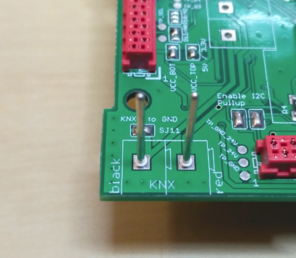
Put in the KNX pins and solder them.
Frontend
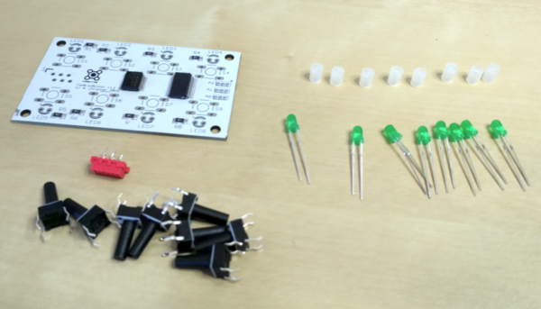
Search the parts you need for the frontend:
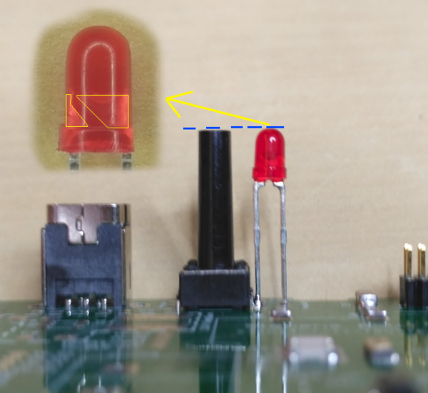
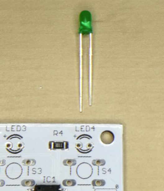
Check the LED polarity. you will have to put in the LED as shown: The long leg with the "tiny part" in the LED is "+", the short leg with the "big part" in the LED is "-" (the other hole on the PCB):
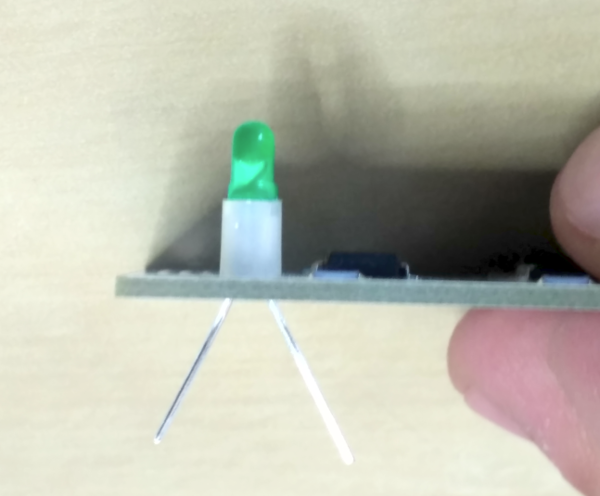
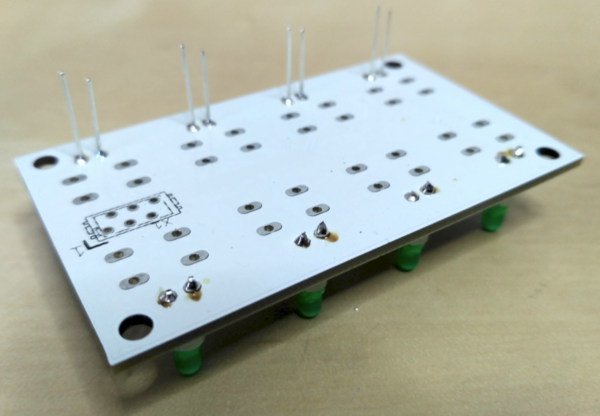
Use the spacer to get the right distance between PCB and LED. You may need to push in the LED quite hard to get a flat sitting LED and spacer. it should finally look like this:
After soldering, cut the LED legs as shown (cut all of them of course ;-) ):
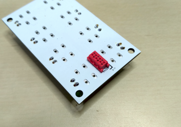
Next you put in the micromatch on the bottom of the PCB like this. If you got a micromatch socket which has the shown gap only on one side, ensure you out it in like shown:
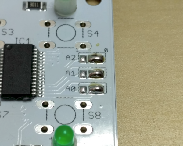
Set the I2C address as shown by putting some solder on the pads. Ensure that solder-jumpers for I2C adress is correctly set to:
A0: 0
A1: 0
A2: 0
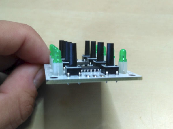
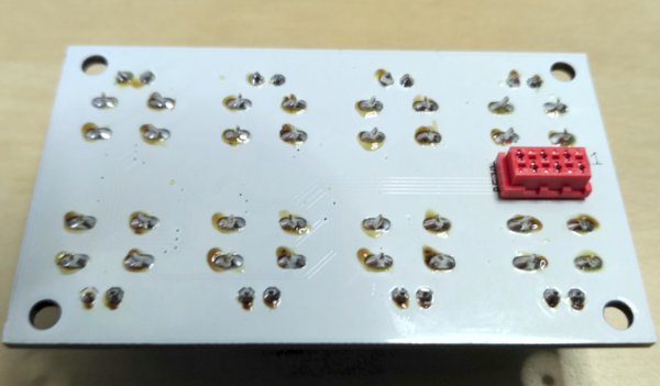
Finally put in the buttons and solder them. Ensure that they are sitting totally flat on the PCB:
If, after soldering, you have a lot of ugly flux on the PCB like this:
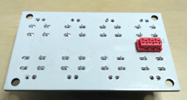
... use some flux cleaner (f.i. plenty of Isopropanol. You get this on Amazon) and an old toothbrush to clean it. Finally it will look like this:
Application
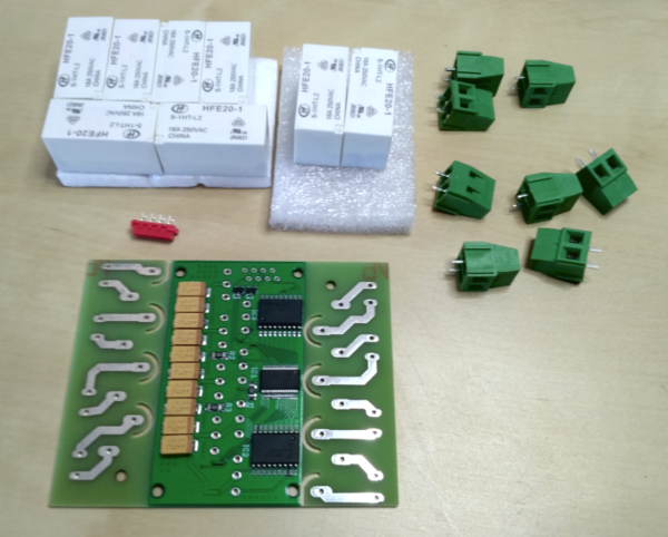
Search all the application PCB required parts, like shown here:
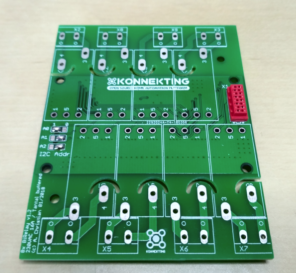
Close the solder jumpers and put in the 2x4 micromatch socket as shown here:
A0: 1
A1: 0
A2: 0
Flip the PCB and solder the micromatch socket.
Next step is to add the screwterminals. Try to align the terminals to the outer PCB line and finally and solder them:
Now we go over to the relays. Put them in place, flip the PCB and solder then:
Try to keep a minimum space between the relays as shown in the image, so that the relays do not touch each other. This is to keep the mechanical stress/vibration of one relay separated from others. You can use a credit card or similar as a kind of separator while soldering.
Mechanical
Connecting PCBs
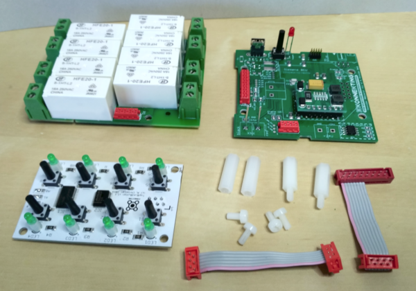
Now that you're done with soldering, you can start to assemble all the parts. You need the following parts for this:
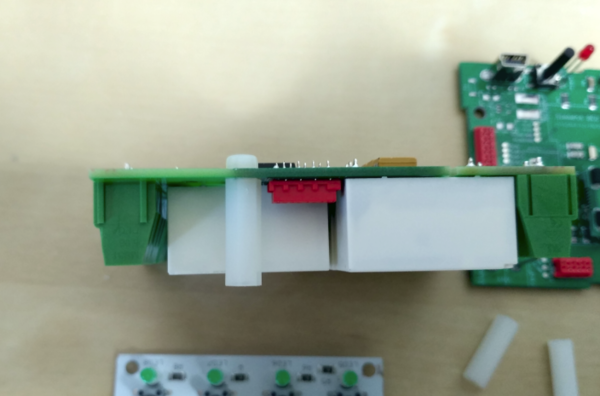
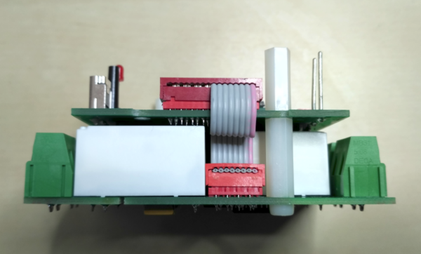
First, take two screws and screw both 18mm hex-spacer to the application PCB as shown:
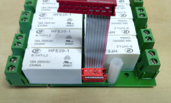
Then take the application-to-controller cable and plug it into the socket on the application PCB:
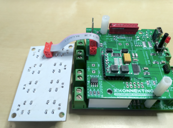
Then take the controller PCB and screw it with help of the 15mm hex-spacer on the application PCBs hex-spacer. Finally connect the cable as shown to the controller PCB.
Now it is time to connect the frontend PCB with the 2x3 micromatch cable. Plug the connector into the socket as shown here:
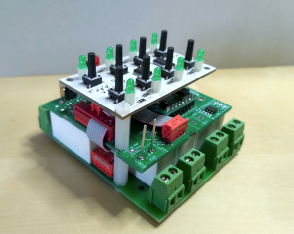
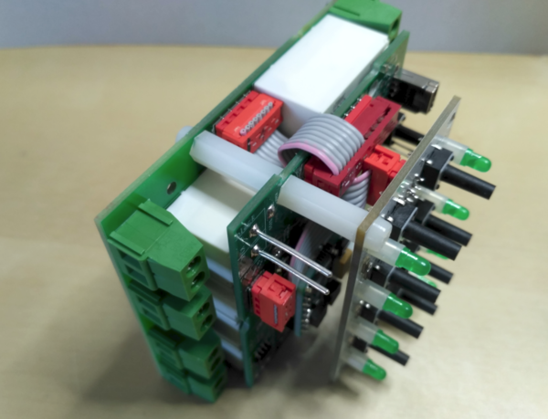
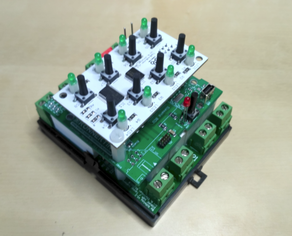
Finally screw the frontend PCB with the remaining two screws on the hex-spacers of the controller PCB:
You're done and screw-connectiond and cables should look like this:
DIN Rail case
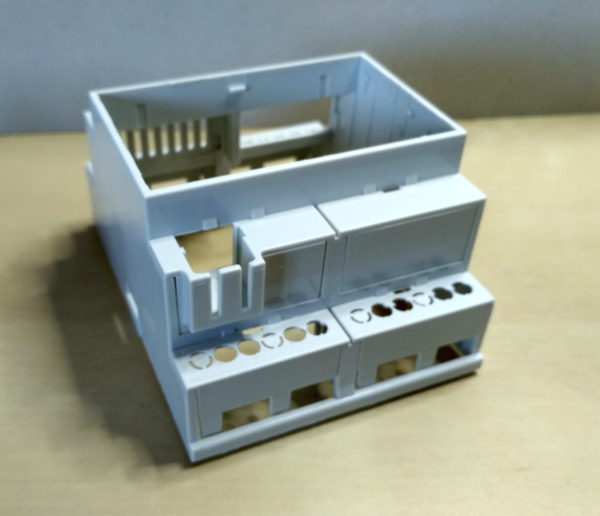
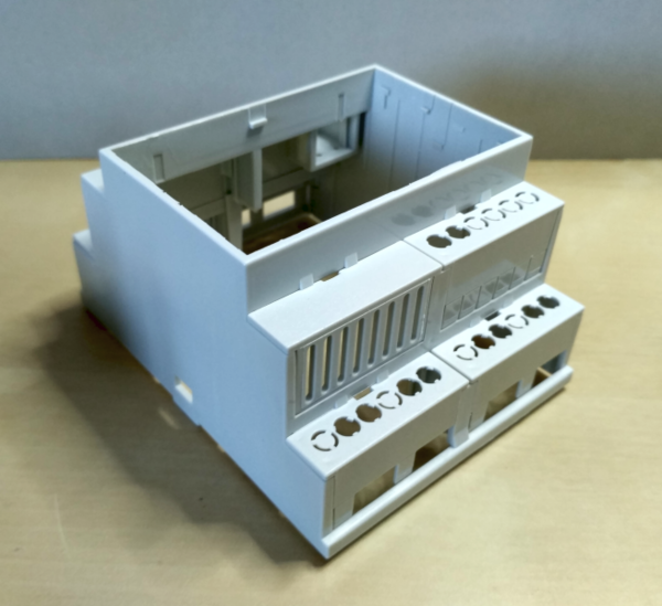
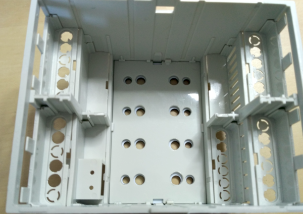
Unpack the case and break out the holes on the terminal covers as shown here:
I recommend using a really sharp knife like a scalpel to cutout the screw-holes. Be careful to not cut too much or break the plastik. The plastik is very soft.
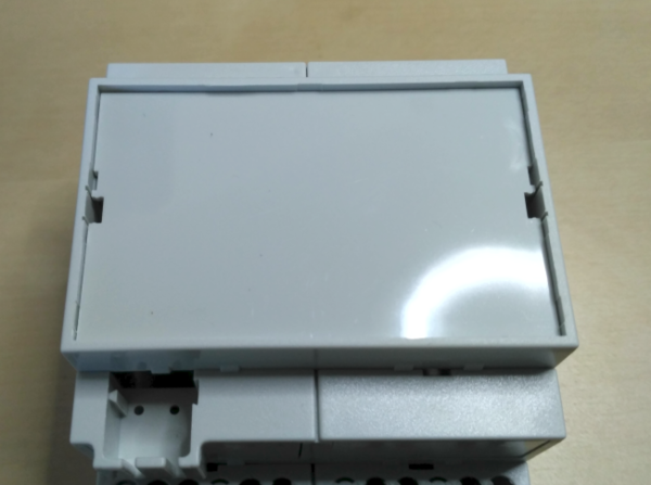
If not already in place, put the plastik cover into the case:
Then put in the cover PCB (it should held itself in place):
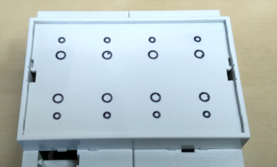
Take a marker pen and mark the holes on the plastic cover as shown:
[[1]]
Remove the cover PCB. Your markings should look like this:
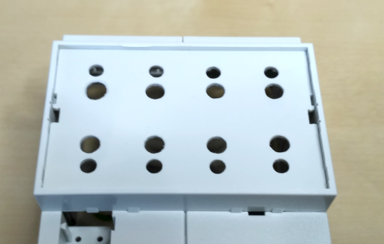
Remove the plastic cover and drill holes on your markings. You shold take a drill that is 2-3mm thicker as the required hole size. Having the drilled holes bigger that the holes in the cover PCB makes it easier for you with centering the drill and also when later on inserting the buttons and LEDs.
I prefer to have the DIN-rail-unlock on the top of the device. If you want the same, ensure that unlock is on the side where the USB connector is. Otherwise take the other side.
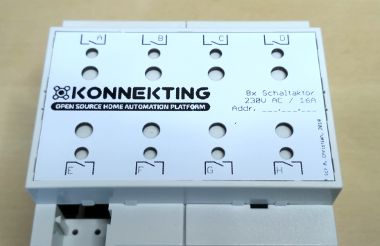
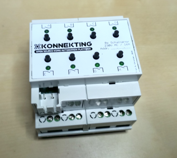
Finally carefully slide the case over. You might need to swap all the terminal covers on the case by 180°: The case does only fit in one direction in the bottom part, as the notches on both sides have different sizes. Now you're done.
