Difference between revisions of "MicroBCU"
Jump to navigation
Jump to search
E.burkowski (talk | contribs) |
|||
| (4 intermediate revisions by one other user not shown) | |||
| Line 1: | Line 1: | ||
{| class="wikitable" style="float:right;margin-left: 15px;margin-top: 15px; margin-bottom: 15px;" | {| class="wikitable" style="float:right;margin-left: 15px;margin-top: 15px; margin-bottom: 15px;" | ||
| − | ! colspan="2"| | + | ! colspan="2"|MicroBCU |
|- | |- | ||
| − | ! colspan="2"|[[File: | + | ! colspan="2"|[[File:MicroBCU_top.png|300px|thumb|center]] |
| + | |- | ||
| + | ! colspan="2"|[[File:MicroBCU_bottom.png|300px|thumb|center]] | ||
|- | |- | ||
! Developer | ! Developer | ||
| − | | | + | | Eugen Burkowski |
|- | |- | ||
! Status | ! Status | ||
| − | | | + | | released |
|- | |- | ||
! Microcontroller/Board | ! Microcontroller/Board | ||
| − | | | + | | universal |
| − | |||
| − | |||
| − | |||
| − | |||
| − | |||
| − | |||
|} | |} | ||
| Line 30: | Line 26: | ||
*Voltage 2 (optinal): 5V (default), can be changed: 3.3V - 21V | *Voltage 2 (optinal): 5V (default), can be changed: 3.3V - 21V | ||
*Max. current: up to 100mA | *Max. current: up to 100mA | ||
| + | *UART: 19200bps 8E1 | ||
== User Documentation == | == User Documentation == | ||
| Line 35: | Line 32: | ||
* 7x pin 2.54mm THT | * 7x pin 2.54mm THT | ||
* 2x4 or 2x5 pin 1.27 SMD | * 2x4 or 2x5 pin 1.27 SMD | ||
| − | [[File:MicroBCU_pins. | + | [[File:MicroBCU_pins.png|378px]] |
Attention: MicroBCU has no dedicated pins for WAGO terminal (Red/Grey)! | Attention: MicroBCU has no dedicated pins for WAGO terminal (Red/Grey)! | ||
| Line 42: | Line 39: | ||
== Build It == | == Build It == | ||
| + | If you solder the MicroBCU yourself, be carefull: | ||
| + | On (some?) PCV Rev 1.2 the solder print on the top (NCN-) side is wrong. | ||
| + | The two capacitors C5 and C6 in the top right corner are switched - here you can see the correct soldering: | ||
| + | |||
| + | https://github.com/KONNEKTING/KonnektingHardware/blob/master/MicroBCU/R1.2/Board_top.pdf | ||
| + | |||
| + | Also be carefull wenn soldering the big capacitor C2: | ||
| + | The solder print marks the + side of the capacitor, because this is the standard for tantalum capacitors. If you use aluminium capacitors, the - side is marked. | ||
== Links == | == Links == | ||
[https://github.com/KONNEKTING/KonnektingHardware/tree/master/MicroBCU] | [https://github.com/KONNEKTING/KonnektingHardware/tree/master/MicroBCU] | ||
| + | [https://knx-user-forum.de/forum/projektforen/konnekting/1045398-microbcu-sehr-kleiner-knx-transceiver] | ||
[[Category:Device/Kits]] | [[Category:Device/Kits]] | ||
Latest revision as of 07:56, 27 August 2019
| MicroBCU | |
|---|---|
| Developer | Eugen Burkowski |
| Status | released |
| Microcontroller/Board | universal |
Description
A little Bus Coupler Unit with an UART interface
Hardware
- IC: NCN5120
- Size: 23 x 19 x 5.4 (10.3) mm
- Voltage 1: 3.3V
- Voltage 2 (optinal): 5V (default), can be changed: 3.3V - 21V
- Max. current: up to 100mA
- UART: 19200bps 8E1
User Documentation
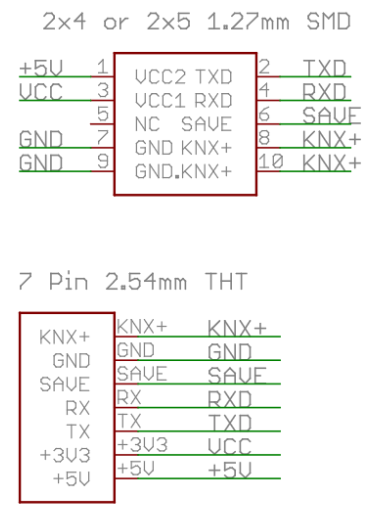
the new version (R1.2) has to connectors:
- 7x pin 2.54mm THT
- 2x4 or 2x5 pin 1.27 SMD
Attention: MicroBCU has no dedicated pins for WAGO terminal (Red/Grey)!
Developer Documentation
Build It
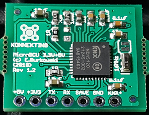
If you solder the MicroBCU yourself, be carefull: On (some?) PCV Rev 1.2 the solder print on the top (NCN-) side is wrong. The two capacitors C5 and C6 in the top right corner are switched - here you can see the correct soldering:
https://github.com/KONNEKTING/KonnektingHardware/blob/master/MicroBCU/R1.2/Board_top.pdf
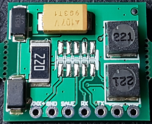
Also be carefull wenn soldering the big capacitor C2: The solder print marks the + side of the capacitor, because this is the standard for tantalum capacitors. If you use aluminium capacitors, the - side is marked.


