Difference between revisions of "MicroBCU2"
Jump to navigation
Jump to search
(→Links) |
|||
| Line 49: | Line 49: | ||
=== Enable High Bus current === | === Enable High Bus current === | ||
| + | For bus current consumption up to 20mA, J3 must be closed (This is the default, closed by a 0R resistor). | ||
| + | |||
| + | For bus current consumption of 10mA or less, J3 can be open. | ||
=== Schematic === | === Schematic === | ||
Revision as of 12:00, 29 November 2020
| MicroBCU2 | |
|---|---|
| Developer | SirSydom |
| Status | beta |
| Version | V00.20 |
| Microcontroller/Board | universal |
Description
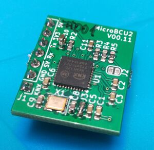
A Bus Coupler Unit (BCU) / KNX Transveiver which supplies the connected device with power from KNX Bus and provides a bus interface at OSI Layer 2.
Hardware
- IC: NCN5120 (ready for NCN5121 / 5130)
- Size: 23 x 19 x 9 mm
- Voltage 1: 3.3V
- Voltage 2 (optional): 5V (default), can be changed: 3.3V - 21V
- Max. current: up to 100mA
- UART: 19200bps 8E1 / 3.3V
User Documentation
Soldering the Kit
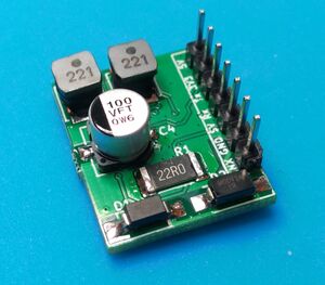
MicroBCU2 comes as a kit where the big parts on the bottom side have to be soldered:
- C4 - 100µF / 35V electrolytic capacitor. Polarization is important, refer to silkscreen or photo
- C41 - 1µF MLCC 1206
- L1 and L2 - 220µH inductors
- R1 - 22R resistor 2512
- J1 - 7x1 2.54 pin header (or whatever you need to connect to your host PCB)
- D1 - SS16 reverse polarity protection diode. . Polarization is important, refer to silkscreen. The bar on the diode should match the bar on silkscreen.
- D2 - SMAJ40CA TVS diode
I recommend to solder the parts in this order: L1, L2, C4, C41, R1, D1, D2, J1
Deactivate / Change VCC2
Enable High Bus current
For bus current consumption up to 20mA, J3 must be closed (This is the default, closed by a 0R resistor).
For bus current consumption of 10mA or less, J3 can be open.

