Difference between revisions of "MicroBCU2"
(→Links) |
|||
| Line 73: | Line 73: | ||
[https://www.google.de/url?sa=t&rct=j&q=&esrc=s&source=web&cd=&cad=rja&uact=8&ved=2ahUKEwjZ_46X2aftAhUxvlkKHbOJCF4QFjAAegQIBBAC&url=https%3A%2F%2Fwww.onsemi.com%2Fpub%2FCollateral%2FNCN5120-D.PDF&usg=AOvVaw0KUimWgup68HXisop9pYTW OnSemi NCN5120 Datasheet] | [https://www.google.de/url?sa=t&rct=j&q=&esrc=s&source=web&cd=&cad=rja&uact=8&ved=2ahUKEwjZ_46X2aftAhUxvlkKHbOJCF4QFjAAegQIBBAC&url=https%3A%2F%2Fwww.onsemi.com%2Fpub%2FCollateral%2FNCN5120-D.PDF&usg=AOvVaw0KUimWgup68HXisop9pYTW OnSemi NCN5120 Datasheet] | ||
| + | |||
| + | [https://gitlab.com/SirSydom/knx_microbcu2 MicroBCU2 on GitLab] | ||
[[Category:Device/Kits]] | [[Category:Device/Kits]] | ||
Revision as of 09:57, 30 November 2020
| MicroBCU2 | |
|---|---|
| Developer | SirSydom |
| Status | beta |
| Version | V00.20 |
| Microcontroller/Board | universal |
Description
A Bus Coupler Unit (BCU) / KNX Transveiver which supplies the connected device with power from KNX Bus and provides a bus interface at OSI Layer 2.
Hardware
- IC: NCN5120 (ready for NCN5121 / 5130)
- Size: 23 x 19 x 9 mm
- Voltage 1: 3.3V
- Voltage 2 (optional): 5V (default), can be changed: 3.3V - 21V
- Max. current: up to 100mA
- UART: 19200bps 8E1 / 3.3V
User Documentation
Soldering the Kit
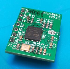
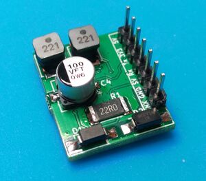
MicroBCU2 comes as a kit where the big parts on the bottom side have to be soldered:
- C4 - 100µF / 35V electrolytic capacitor. Polarization is important, refer to silkscreen or photo
- C41 - 1µF MLCC 1206
- L1 and L2 - 220µH inductors
- R1 - 22R resistor 2512
- J1 - 7x1 2.54 pin header (or whatever you need to connect to your host PCB)
- D1 - SS16 reverse polarity protection diode. . Polarization is important, refer to silkscreen. The bar on the diode should match the bar on silkscreen.
- D2 - SMAJ40CA TVS diode
I recommend to solder the parts in this order: L1, L2, C4, C41, R1, D1, D2, J1
Deactivate / Change VCC2
If you want to get rid of VCC2, L2, R3, R4, R5, C11 and C111 are not needed. Close J2 in that case.
To change VCC2, change R4 and R5 according the NCN5120 dataheet. When VCC2 is greater than 10V, C11 must be changed so that the voltage rating matches or exceeds VCC2 (e.g. when VCC2 = 12V, use a 16V MLCC)
Enable High Bus current
For bus current consumption up to 20mA, J3 must be closed (This is the default, closed by a 0R resistor).
For bus current consumption of 10mA or less, J3 can be open.
Schematic
KiCad
Developer Documentation
Version history
- V00.11 - first prototype series
- V00.20 - second prototype series

