Difference between revisions of "KONNEKTING Modular DIN RAIL Device Specification"
Konnekting (talk | contribs) |
Konnekting (talk | contribs) (→BOM) |
||
| Line 29: | Line 29: | ||
|https://www.buerklin.com/de/RAILTEC-B-4-Module-Ausf-VI/p/30H2334 | |https://www.buerklin.com/de/RAILTEC-B-4-Module-Ausf-VI/p/30H2334 | ||
|- | |- | ||
| − | | | + | |[[File:OKW-B6607145.png|200px|thumb|left|B6607145]] |
|KNX COVER, FLAT | |KNX COVER, FLAT | ||
|B6607145 | |B6607145 | ||
Revision as of 09:40, 15 February 2021
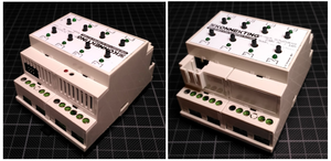
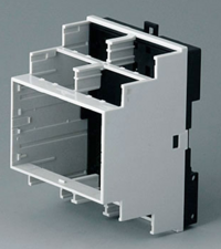
Din Rail Case
Manufacturer: https://www.okw.com
Part: Railtec B - 4 TE / https://www.okw.com/de/Railtec-B/B6503121.htm?var=c9f11140-cb2e-11e3-89f9-00163e72470b
The case can be ordered directly from OKW. But keep in mind that you should reach 100EUR netto to overcome additional shipping fees. Your can also order the case at buerklin.com without the 100EUR limit. Just search for the OKW part-number with the search on the Bürklin web page.
Example:
BOM
Mechanical
The OKW case allows PCBs on 3 levels. From top to bottom we name them:
- Frontend PCB
- Controller PCB
- Application PCB
The PCBs are scred together with M3 hex-spacers. Here's a mechanical overview (from top to bottom):
[2mm space to outer case edge]
[1,6mm inner OKW Railtec cover]
[6,1mm free space to inner OKW Railtec lid] → top-edge inner lid to top-edge frontend pcb = 7,7mm
[1,6mm Frontend PCB]
[15mm M3 hex spacer]
[1,6mm Controller PCB]
[18mm M3 hex spacer]
[1,6mm Application PCB]
[3,5mm screw pin on black OKW Railtec base plate]
Recommendation for tactile push button Frontend PCB: 9,5mm height.
5mm LED PCB spacer for 3mm THT LEDs: http://www.reichelt.de/Zubehoer-fuer-LEDs/MEN-2818-3045/3/index.html?ACTION=3&LA=446&ARTICLE=62820&GROUPID=3044&artnr=MEN+2818.3045&SEARCH=led%2Babstandshalter
→ the LED protrudes about 2mm out of the cover lid.
→ Use 4mm led spacer to reduce this to 1mm
You can use a plain PCB with silkscreen printing and wholes to create a nice looking cover, that sits on the OKW Railtec lid. This will also fill the remaining space to the outer case edge on top of the OKW lid.
Reference controller
See M0dularis+
Interconnections
Controller: Application Socket
The controller PCB must use a 2x4 or 2x8 micromatch socket.
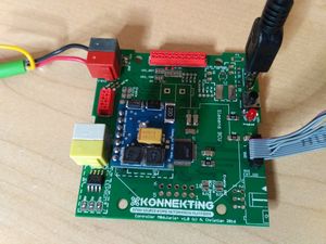
Example controller PCB (on top: application socket, on left: frontend socket):
Pinout:
| Description | Pin | Pin | Description |
|---|---|---|---|
| GND / KNX GND | 1 | 2 | GND from 24V Input |
| VCC | 3 | 4 | 24V from 24V Input |
| SDA / IO0 | 5 | 6 | IO3 |
| SCL / IO1 | 7 | 8 | ExtINT Application / IO2 |
| Option0 | 9 | 10 | Option7 |
| Option1 | 11 | 12 | Option6 |
| Option2 | 13 | 14 | Option5 |
| Option3 | 15 | 16 | Option4 |
Remarks:
- Option0..7: Freely selectable, depends on the controller. If not used at all: Stick to Pin1..8 and apply a 2x4 micromatch socket only.
- IO0..IO3: Freely selectable, but:
- SDA/SCL: This pins must have I2C capabilities
- ExtINT: This pin must have interrupt capabilities
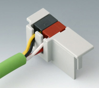
- 24V Input: 24V DC supply voltage from separate socket with white/yellow wire pair
- GND: relative to VCC
- GND 24V: relative to 24V DC Input
- VCC: 3.3V or 5V, depending on the controller, if possible, selectable with jumper/solderjumper
Controller: Frontend Application Socket
| Description | Pin | Pin | Description |
|---|---|---|---|
| GND | 1 | 2 | SDA |
| VCC | 3 | 4 | SCL |
| unused/reserve | 5 | 6 | ExtINT Frontend |
Remarks:
- See Application Connector above
Controller: Extension Socket
KONNEKTING (talk) not yet fully specified. work in progress


