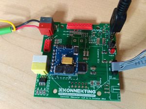
M0dularis+
| M0dularis+ | |
|---|---|
| Developer | Alexander Christian |
| Status/Current Version | Version 1.0 already works |
| µC | Atmel/Microchip SAMD21G18J |
| KNX | Siemens BCU / Micro BCU |
Description
Controller-Board, mainly designed for OKW 4TE REG case, but also useable with anything else that fits. Can be used with Siemens BCU and Eugen's µBCU. Uses the powerful SAMD21 microcontroller from Microchip/Atmel and has optional I²C EEPROM and SPI Flash.
Hardware
This controller uses microcontroller IC as the Arduino Zero (https://store.arduino.cc/usa/arduino-zero). So you can use it almost the same way. The only difference:
- no EDBG connector
- different formfactor and connectors
- and therefore, not all pins available
The design principle was: Get the most of out of the Arduino Zero (wrt Pins and Features) and fit into the modular concept of KONNEKTING. Everything that is not available, can be added via I2C or SPI or UART. So even if there are not much PWM capable pins available (which won't let you build a 16 channel PWM dimmer), you can add PWM via I2C. Same counts for general purpose IO pins.
Application Connector
| Description | Pin | Pin | Description | ||||||||
|---|---|---|---|---|---|---|---|---|---|---|---|
| GND / KNX GND | 1 | 2 | GND from 24V Input | ||||||||
| SJ: 3.3V or 5V | VCC | 3 | 4 | 24V from 24V Input | |||||||
| TX3 | PA22 / SDA | SDA / IO0 | 5 | 6 | IO3 | SJ: PA19/D12* or PA02/A0 | MISO1 | RX1 | |||
| RX3 | PA23 / SCL | SCL / IO1 | 7 | 8 | ExtINT Application / IO2 | SJ: PA18/D10* or PB09/A2 | SS1 | TX1 | |||
| SDA2 | RX2 | MISO2 | PA09/D3* | Option0 | 9 | 10 | Option7 | PA17/D13* | SCK1 | RX1 | SCL1 |
| SCL2 | TX2 | MOSI2 | PA08/D4* | Option1 | 11 | 12 | Option6 | PA16/D11* | MOSI1 | TX1 | SDA1 |
| SCK2 | PA15/D5* | Option2 | 13 | 14 | Option5 | PA20/D6* | |||||
| SS2 | PA14/D2* | Option3 | 15 | 16 | Option4 | PA21/D7* |
You can configure different settings via solder-jumper (SJ):
- IO3: D12 or A0
- IO2: D10 or A2
- Application connector: 5V or 3.3V
- Frontend connector: 5V or 3.3V
- I2C (on IO0/IO1): PullUp or NoPullUp
OnBoard Connections
- ProgButton*: D15 / A1 [EIC8]
- ProgLED: D19 / A5
- BCU Save*: D17 / A3 [EIC4]
- BCU Reset*: Solder jumper for connecting SAMD-RESET and BCU-RESET Pin
- ExtInt TOP*: D38 [EIC13]
- SPI Flash
- CS: D9
- DO/IO1: PA12 / D22 MISO
- DI/IO0: PB10 / D23 MOSI
- CLK: PB11 / D24 SCK
* = PWM capable
Developer Documentation
How to use SPI Flash
I recommend to use this SPI Flash Library: https://github.com/Marzogh/SPIFlash
You need to explicitly tell the library the CS-Pin:
1// set CS pin to D9
2SPIFlash flash(9);
For testing, you can use https://github.com/Marzogh/SPIFlash/tree/development/examples/TestFlash and modify the said line to use the custom CS pin D9.
