Difference between revisions of "16CH Binary Input"
| Line 71: | Line 71: | ||
'''Mounting Kit''' | '''Mounting Kit''' | ||
| − | + | 1x Micromatch cable | |
| + | 8x Screws | ||
| + | |||
Revision as of 15:10, 1 March 2018
| 16CH Binary Input | |
|---|---|
| Developer | Matthias F. |
| Status | Version 1.0 finished |
| Microcontroller/Board | |
| KNX connectivity | Mini-BCU |


Description
16ch Binary Input (potential-free)
The binary input has 16 inputs available and is used to connect eight conventional push-buttons or floating contacts such as window or relay contacts. There is one status LED for each input. In addition, the input status is sent to the bus. A separate power supply is not necessary
Technical Data:
- Operating voltage: KNX Bus voltage <10mA
- Installation type: Top Hat Rail mounting
- Number of Inputs: 16
- Number of S0-Inputs: 4 (CH13 - CH16)
- Input polling: with 100ms, 300ms or 500ms
- Typ of Inputs: potential-free / floating contacts
- Max. cable length: 30m tested (more possible)
- input voltage: 5V
- Max. input voltage: 24V (absolute rating, for <1min)
- Max. input current: 10mA
- The device makes a contact supply voltage (5V) which is not electrically isolated from the bus voltage!
- x-Inputs can configure to a "room" ("room"-GA can show if one of the windows is open in the room)
Schematic

Hardware
What you need
for this device do you need:
- 1x OKW Housing
- 1x PCB Kit
- 1x Mounting Kit (screws, ...)
OKW Housing link OKW-Website:[1]
1x B6503121 RAILTEC B, 4 Module
3x B6607140 Klemmenabdeckung, flach
1x B6607145 Abdeckung KNX, flach
4x B6607142 Klemmenabdeckung, flach
(1x) B6603180 Frontplatte, 4 Module (only if you don't use the "LED-Status-PCB"
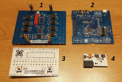
PCB Kit:
1) Application PCB
2) Controller PCB
3) LED-Status PCB (for function not necessary, only to show the status of the Inputs)
4) Mini-BCU (KNX-Transceiver)

Mounting Kit
1x Micromatch cable
8x Screws

Software
What you need
- Arduino IDE (link)
- Arduino Code for 16CH Binary Input
- XML-File for 16CH Binary Input
- KONNEKTING SUITE (link)
Arduino Code
XML-File
User Documentation
SW Documentation
Sperrobjekte
Room classification
HW Documentation
Circuit diagram
One VCC Output-Pin shares two Input-Channels. Because of that always two Channels will monitoring together.
S0 interface Up to four Inputs can configure to an S0-interface. possible CH are Ch13 - Ch16 note: If you configure only one Ch to an S0-Interface on an VCC-Output pair, then the output of the other CH can not be switched off, because the VCC-Output voltage supply always both Channels.


Developer Documentation
State Machine
START -> Loop over all Channels (activation Outputs x + y -> readout inputs x + y -> update Status LED -> deactivation Outputs x + y)