Difference between revisions of "16CH Binary Input"
| Line 81: | Line 81: | ||
=== Block Diagramm === | === Block Diagramm === | ||
| − | + | [[File:16CH Binary INput Block Diagramm.PNG]] | |
== Schematic == | == Schematic == | ||
Revision as of 17:30, 2 March 2018
| 16CH Binary Input | |
|---|---|
| Developer | Matthias F. |
| Status | Version 1.0 finished |
| Microcontroller/Board | |
| KNX connectivity | Mini-BCU |


Description
16ch Binary Input (potential-free)
The binary input has 16 inputs available and is used to connect eight conventional push-buttons or floating contacts such as window or relay contacts. There is one status LED for each input. In addition, the input status is sent to the bus. A separate power supply is not necessary
Technical Data:
- Operating voltage: KNX Bus voltage <10mA
- Installation type: Top Hat Rail mounting
- Number of Inputs: 16
- Number of S0-Inputs: 4 (CH13 - CH16)
- Input polling: with 100ms, 300ms or 500ms
- Typ of Inputs: potential-free / floating contacts
- Max. cable length: 30m tested (more possible)
- input voltage: 5V
- Max. input voltage: 24V (absolute rating, for <1min)
- Max. input current: 10mA
- The device makes a contact supply voltage (5V) which is not electrically isolated from the bus voltage!
- x-Inputs can configure to a "room" ("room"-GA can show if one of the windows is open in the room)
Hardware
What you need
for this device do you need:
- 1x OKW Housing
- 1x PCB Kit
- 1x Mounting Kit (screws, ...)
OKW Housing link OKW-Website:[1]
1x B6503121 RAILTEC B, 4 Module
3x B6607140 Klemmenabdeckung, flach
1x B6607145 Abdeckung KNX, flach
4x B6607142 Klemmenabdeckung, flach
(1x) B6603180 Frontplatte, 4 Module (only if you don't use the "LED-Status-PCB"
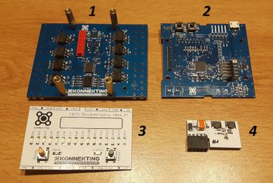
PCB Kit:
1) Application PCB
2) Controller PCB
3) LED-Status PCB (for function not necessary, only to show the status of the Inputs)
4) Mini-BCU (KNX-Transceiver)

Mounting Kit
1x Micromatch cable
8x Screws

Block Diagramm

Schematic

Software
What you need
- Arduino IDE (link)
- Arduino Code for 16CH Binary Input
- XML-File for 16CH Binary Input
- KONNEKTING SUITE (link)
Arduino Code
XML-File
User Documentation
SW Documentation
Sperrobjekte
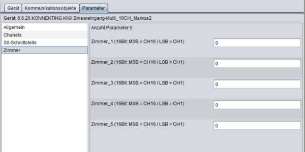
Room classification
Die Raumerkennung funktioniert als 16Bit Wert und jedes Bit ist ein Input. Möchte man also alle 16 Inputs zusammen als "Zimmer" definieren, dann wäre das:
b1111111111111111 = 65535
oder frei, Inputs wären hier: 1,5,6,10,14,15
b1000110001000110 = 35910
Die Dezimalwerte kann man in die Suite eingeben, beim parameterisieren werden diese Werte ins EEPROM geschrieben. Bei jedem Start werden die Daten ins RAM geladen und decodiert.
Aktuell können so 5 "Zimmer" definiert werden

HW Documentation
Circuit diagram
One VCC Output-Pin shares two Input-Channels. Because of that always two Channels will monitoring together.
S0 interface Up to four Inputs can configure to an S0-interface. possible CH are Ch13 - Ch16 note: If you configure only one Ch to an S0-Interface on an VCC-Output pair, then the output of the other CH can not be switched off, because the VCC-Output voltage supply always both Channels.


Developer Documentation
State Machine
START -> Loop over all Channels (activation Outputs x + y -> readout inputs x + y -> update Status LED -> deactivation Outputs x + y)