Difference between revisions of "DFF4.1"
Konnekting (talk | contribs) |
Konnekting (talk | contribs) |
||
| Line 22: | Line 22: | ||
The purpose of this actuator is, to control Roto Rototronic skylight with shutters and/or sun blinds. | The purpose of this actuator is, to control Roto Rototronic skylight with shutters and/or sun blinds. | ||
It has 4 "channels". Each channel internally uses two relays: One for the open-action, and one for the close-action. | It has 4 "channels". Each channel internally uses two relays: One for the open-action, and one for the close-action. | ||
| + | |||
| + | Of course you can also control your Roto Rototronic skylight with help of a standard switch-actuator. But then you don't have the possibility to "open the window 75%" or "close the shutter 80%". The firmware for DFF4.1 provides all this neat feature that you know from typical shutter/blinds actuators. | ||
| + | |||
| + | == Hardware == | ||
This actuator consists of the following REG parts: | This actuator consists of the following REG parts: | ||
| Line 29: | Line 33: | ||
* [[ 8 Relay Bistable | 8x Relay Bistable, bus powered ]] (8 relays in total, 2 for each channel = 4 channels). | * [[ 8 Relay Bistable | 8x Relay Bistable, bus powered ]] (8 relays in total, 2 for each channel = 4 channels). | ||
| − | + | I2C address on application board: | |
| + | |||
| + | A0: 1 | ||
| + | A1: 0 | ||
| + | A2: 0 | ||
| + | |||
| + | I2C address on frontend board: | ||
| + | |||
| + | A0: 0 | ||
| + | A1: 0 | ||
| + | A2: 0 | ||
| − | |||
== Software == | == Software == | ||
| Line 39: | Line 52: | ||
== Developer Documentation == | == Developer Documentation == | ||
| − | + | Firmware sourcecode is on github: https://github.com/KONNEKTING/KonnektingFirmware/tree/master/DFF4.1_1.0 | |
| + | You can't build it yourself, as it depends on KONNEKTING Device Library somewhere between beta4 and beta5 :-( | ||
| − | |||
| − | + | == Build It == | |
| − | |||
| − | |||
| − | + | This actuator uses three PCBs, a bunch of SMD components as well as a lot of mechanical parts. As most users are not able to solder SMD, the PCBs are pre-soldered with all SMD components. Due to the big amount of parts, this actuator comes as a DIY kit: You have to solder non-SMD parts yourself and build up the device and finally flash the firmware with help of a USB connection. | |
| − | + | Check here for the [[DFF4.1 Building Instructions]] | |
| − | |||
| − | |||
Revision as of 08:35, 6 April 2018
| DFF4.1 | |
|---|---|
| Developer | Alexander Christian |
| Status | Version 1.0 finished |
| Microcontroller/Board | M0dularisM+ |
| KNX connectivity | Siemens BCU, Eugen's µBCU |
Description
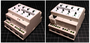
The purpose of this actuator is, to control Roto Rototronic skylight with shutters and/or sun blinds. It has 4 "channels". Each channel internally uses two relays: One for the open-action, and one for the close-action.
Of course you can also control your Roto Rototronic skylight with help of a standard switch-actuator. But then you don't have the possibility to "open the window 75%" or "close the shutter 80%". The firmware for DFF4.1 provides all this neat feature that you know from typical shutter/blinds actuators.
Hardware
This actuator consists of the following REG parts:
- M0dularis+
- 8x Button + 8x LED
- 8x Relay Bistable, bus powered (8 relays in total, 2 for each channel = 4 channels).
I2C address on application board:
A0: 1
A1: 0
A2: 0
I2C address on frontend board:
A0: 0
A1: 0
A2: 0
Software
User Documentation
Developer Documentation
Firmware sourcecode is on github: https://github.com/KONNEKTING/KonnektingFirmware/tree/master/DFF4.1_1.0 You can't build it yourself, as it depends on KONNEKTING Device Library somewhere between beta4 and beta5 :-(
Build It
This actuator uses three PCBs, a bunch of SMD components as well as a lot of mechanical parts. As most users are not able to solder SMD, the PCBs are pre-soldered with all SMD components. Due to the big amount of parts, this actuator comes as a DIY kit: You have to solder non-SMD parts yourself and build up the device and finally flash the firmware with help of a USB connection.
Check here for the DFF4.1 Building Instructions
