Uncategorized files
Jump to navigation
Jump to search
Showing below up to 50 results in range #21 to #70.
View (previous 50 | next 50) (20 | 50 | 100 | 250 | 500)
 DFF4.1 Building Instruction applicationsolderedterminals.png 689 × 487; 459 KB
 DFF4.1 Building Instruction assembledmicromatch.png 1,114 × 583; 718 KB
 DFF4.1 Building Instruction assemblyapplicationcable.png 768 × 464; 455 KB
 DFF4.1 Building Instruction assemblybottom.png 704 × 465; 336 KB
 DFF4.1 Building Instruction assemblycase1.png 737 × 594; 510 KB
 DFF4.1 Building Instruction assemblycase2.png 591 × 528; 317 KB
 DFF4.1 Building Instruction assemblycasecover1.png 651 × 485; 303 KB
 DFF4.1 Building Instruction assemblycasecover2.png 548 × 355; 196 KB
 DFF4.1 Building Instruction assemblycasecover3.png 809 × 591; 488 KB
 DFF4.1 Building Instruction assemblycasecover4.png 540 × 326; 153 KB
 DFF4.1 Building Instruction assemblycasecover5.png 547 × 348; 163 KB
 DFF4.1 Building Instruction assemblycasecover6.png 790 × 558; 545 KB
 DFF4.1 Building Instruction assemblycasecutouts1.png 656 × 564; 420 KB
 DFF4.1 Building Instruction assemblycasecutouts2.png 655 × 599; 438 KB
 DFF4.1 Building Instruction assemblycomplete.png 734 × 583; 507 KB
 DFF4.1 Building Instruction assemblycompletedetail.png 776 × 594; 523 KB
 DFF4.1 Building Instruction assemblycontroller.png 771 × 465; 340 KB
 DFF4.1 Building Instruction assemblyfrontendcable.png 794 × 586; 609 KB
 DFF4.1 Building Instruction assemblyparts.png 788 × 552; 565 KB
 DFF4.1 Building Instruction cutmicromatchorientationpin.png 1,050 × 562; 667 KB
 DFF4.1 Building Instruction cutribboncable.png 1,123 × 624; 770 KB
 DFF4.1 Building Instruction frontendbuttonsalignment.png 626 × 467; 291 KB
 DFF4.1 Building Instruction frontendcutledpins.png 781 × 541; 479 KB
 DFF4.1 Building Instruction frontendflux.png 755 × 442; 349 KB
 DFF4.1 Building Instruction frontendfluxremoved.png 744 × 398; 289 KB
 DFF4.1 Building Instruction frontendi2caddress.png 660 × 527; 437 KB
 DFF4.1 Building Instruction frontendledalignment.png 647 × 535; 294 KB
 DFF4.1 Building Instruction frontendledorientation.png 527 × 613; 401 KB
 DFF4.1 Building Instruction frontendmicromatch.png 729 × 510; 407 KB
 DFF4.1 Building Instruction frontendparts.png 795 × 454; 442 KB
 DFF4.1 Building Instruction knxpins.png 639 × 558; 434 KB
 DFF4.1 Building Instruction microbcu.png 833 × 585; 744 KB
 DFF4.1 Building Instruction micromatchcrimp.png 1,142 × 832; 910 KB
 DFF4.1 Building Instruction micromatchsocket.png 973 × 823; 1.13 MB
 DFF4.1 Building Instruction sjcontroller.png 870 × 771; 1,004 KB
 DFF4.1 Circuit Diagram.png 597 × 786; 220 KB
 DIM-24CVLED 01 wo case front.jpeg 1,435 × 631; 592 KB
 DIM-24CVLED 01 wo case top.jpeg 1,801 × 982; 879 KB
 EDS-WS433.01 HW001.jpg 915 × 651; 442 KB
 EDS WS433 W132 W174 Sensors.jpg 322 × 772; 344 KB
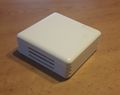 EnOcean Gateway Case close.jpg 2,482 × 1,960; 661 KB
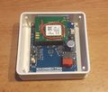 EnOcean Gateway Case open.jpg 2,161 × 1,844; 730 KB
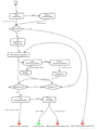
 Flow write all.png 1,184 × 2,141; 294 KB
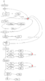
 Flow write individual address.png 943 × 1,274; 144 KB
 HW1.2 SolderJumper.png 1,280 × 720; 1.1 MB
 HW1.2 on BCU.PNG 987 × 638; 1.46 MB
 IMG 20190826 065357703.jpg 3,264 × 1,836; 1.77 MB
 KRS-XL CB6-9-12.V01.00 schematic.pdf ; 168 KB
 KRS-XL DIM-24CVLED insights.jpeg 1,632 × 918; 876 KB
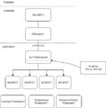 LEDD4.1 blockdiagram.drawio.png 501 × 511; 24 KB


