Uncategorized files
Jump to navigation
Jump to search
Showing below up to 50 results in range #1 to #50.
View (previous 50 | next 50) (20 | 50 | 100 | 250 | 500)
- 1-Wire Gateway Firmware10 Overview.PNG 1,167 × 656; 88 KB
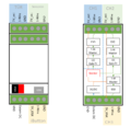
- 1-Wire Gateway Hardware BlockDiagram.PNG 268 × 634; 21 KB
- 1-Wire Gateway Overview Picture.PNG 653 × 632; 37 KB
- 16CH Binary INput Block Diagramm.PNG 925 × 749; 53 KB
- 16CH Binary Input Application PCB Bausatz.jpg 3,274 × 2,590; 1.67 MB
- 16CH Binary Input Overview.jpg 3,984 × 1,514; 1.17 MB
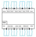
- 16CH Binary Input Overview Inputs.jpg 631 × 644; 87 KB
- 16CH Binary Input PCB Stacked.jpg 4,608 × 2,592; 3.59 MB
- 16CH Binary Input PCBs.jpg 3,460 × 2,328; 2.74 MB
- 16CH Binary Input Schematic.png 826 × 455; 149 KB
- 16CH Binary Input Suite ZimmerErkennung.PNG 830 × 415; 57 KB
- 16CH Binary Input comp.jpg 911 × 795; 83 KB
- 20180212 Powered by KONNEKTING.png 400 × 72; 11 KB
- 20180212 Powered by KONNEKTING with K logo.png 400 × 69; 12 KB
- Crowduino-m0-sd.jpg 1,000 × 1,000; 440 KB
- DFF4.1 1.0.png 997 × 484; 509 KB
- DFF4.1 Building Instruction LedAndButton.png 654 × 601; 427 KB
- DFF4.1 Building Instruction applicationi2caddress.png 595 × 549; 455 KB
- DFF4.1 Building Instruction applicationparts.png 718 × 577; 548 KB
- DFF4.1 Building Instruction applicationrelays.png 546 × 552; 359 KB
- DFF4.1 Building Instruction applicationsolderedterminals.png 689 × 487; 459 KB
- DFF4.1 Building Instruction assembledmicromatch.png 1,114 × 583; 718 KB
- DFF4.1 Building Instruction assemblyapplicationcable.png 768 × 464; 455 KB
- DFF4.1 Building Instruction assemblybottom.png 704 × 465; 336 KB
- DFF4.1 Building Instruction assemblycase1.png 737 × 594; 510 KB
- DFF4.1 Building Instruction assemblycase2.png 591 × 528; 317 KB
- DFF4.1 Building Instruction assemblycasecover1.png 651 × 485; 303 KB
- DFF4.1 Building Instruction assemblycasecover2.png 548 × 355; 196 KB
- DFF4.1 Building Instruction assemblycasecover3.png 809 × 591; 488 KB
- DFF4.1 Building Instruction assemblycasecover4.png 540 × 326; 153 KB
- DFF4.1 Building Instruction assemblycasecover5.png 547 × 348; 163 KB
- DFF4.1 Building Instruction assemblycasecover6.png 790 × 558; 545 KB
- DFF4.1 Building Instruction assemblycasecutouts1.png 656 × 564; 420 KB
- DFF4.1 Building Instruction assemblycasecutouts2.png 655 × 599; 438 KB
- DFF4.1 Building Instruction assemblycomplete.png 734 × 583; 507 KB
- DFF4.1 Building Instruction assemblycompletedetail.png 776 × 594; 523 KB
- DFF4.1 Building Instruction assemblycontroller.png 771 × 465; 340 KB
- DFF4.1 Building Instruction assemblyfrontendcable.png 794 × 586; 609 KB
- DFF4.1 Building Instruction assemblyparts.png 788 × 552; 565 KB
- DFF4.1 Building Instruction cutmicromatchorientationpin.png 1,050 × 562; 667 KB
- DFF4.1 Building Instruction cutribboncable.png 1,123 × 624; 770 KB
- DFF4.1 Building Instruction frontendbuttonsalignment.png 626 × 467; 291 KB
- DFF4.1 Building Instruction frontendcutledpins.png 781 × 541; 479 KB
- DFF4.1 Building Instruction frontendflux.png 755 × 442; 349 KB
- DFF4.1 Building Instruction frontendfluxremoved.png 744 × 398; 289 KB
- DFF4.1 Building Instruction frontendi2caddress.png 660 × 527; 437 KB
- DFF4.1 Building Instruction frontendledalignment.png 647 × 535; 294 KB
- DFF4.1 Building Instruction frontendledorientation.png 527 × 613; 401 KB
- DFF4.1 Building Instruction frontendmicromatch.png 729 × 510; 407 KB
- DFF4.1 Building Instruction frontendparts.png 795 × 454; 442 KB


