Difference between revisions of "Modular LED Dimmer 1-12CH"
(Created page with "{| class="wikitable" style="float:right;margin-left: auto; margin-right: 0px;" ! colspan="2"|Modular LED Dimmer 1-12CH |- ! colspan="2"|Picture |- ! Developer | SirSydom |- !...") |
|||
| (9 intermediate revisions by 2 users not shown) | |||
| Line 1: | Line 1: | ||
| − | {| class="wikitable" style="float:right;margin-left: | + | {| class="wikitable" style="float:right;margin-left: 15px;margin-top: 15px; margin-bottom: 15px;" |
! colspan="2"|Modular LED Dimmer 1-12CH | ! colspan="2"|Modular LED Dimmer 1-12CH | ||
|- | |- | ||
| − | ! colspan="2"| | + | ! colspan="2"|[[File:Modular led dimmer proto01.jpg|300px|thumb|center]] |
|- | |- | ||
! Developer | ! Developer | ||
| − | | SirSydom | + | | [http://wiki.konnekting.de/index.php/User:SirSydom SirSydom] |
|- | |- | ||
! Phase | ! Phase | ||
| − | | | + | | Beta Version in productive environment |
|- | |- | ||
! µC-Board | ! µC-Board | ||
| − | | Arduino Pro Mini/Pro Micro/Micro/Mega 2560 | + | | Arduino Pro Mini/Pro Micro/Micro/Mega 2560/ItsyBitsyM0 |
|- | |- | ||
! µC | ! µC | ||
| − | | atmega328p/atmega32u4/atmega 2560 | + | | atmega328p/atmega32u4/atmega 2560/SAMD21 |
|- | |- | ||
! KNX | ! KNX | ||
| − | | | + | | [[SiemensBCU]] / [[MiniBCU]] / [[MicroBCU]] |
|} | |} | ||
| Line 23: | Line 23: | ||
== Short Description == | == Short Description == | ||
The idea behind this "device" is to create a common software and hardware design, to enable the advanced user to build a custom LED-Dimmer. | The idea behind this "device" is to create a common software and hardware design, to enable the advanced user to build a custom LED-Dimmer. | ||
| − | Soldering and PCB will be limited to Breadboard. | + | |
| + | Soldering and PCB will be limited to Breadboard, so everyone who knows which side of the soldering iron will get hot can build it. | ||
| + | |||
It will support a range of 1 up to 12 channels using the 16bit timer/pwm of the atmega µControllers. | It will support a range of 1 up to 12 channels using the 16bit timer/pwm of the atmega µControllers. | ||
| + | |||
Depending on the number of channels, it can be built into a REG-Case for central usage or into module case for decentral usage. | Depending on the number of channels, it can be built into a REG-Case for central usage or into module case for decentral usage. | ||
| + | |||
It will support CV (constant voltage) LED up to 24V and CC (constant current) LED. | It will support CV (constant voltage) LED up to 24V and CC (constant current) LED. | ||
| + | |||
| + | Maybe for some configurations I (or someone else) will design a pcb. | ||
| + | |||
| + | |||
| + | While the current prototype runs on a Mega2560 Board, I plan switiching to SAMD21 on a ItsyBitsyM0 Board with MicroBCU and a PCA9685 I2C PWM Driver. | ||
| + | With this setup 24 channels in a 9TE casing seem to be possible. | ||
| Line 38: | Line 48: | ||
== Build It == | == Build It == | ||
| + | |||
| + | |||
| + | == Links == | ||
| + | |||
| + | [https://knx-user-forum.de/forum/%C3%B6ffentlicher-bereich/knx-eib-forum/diy-do-it-yourself/1179151-cc-led-dimmen KNXUF Thread CC LED dimmen] | ||
| + | |||
| + | [https://knx-user-forum.de/forum/projektforen/konnekting/1166807-grunds%C3%A4tzliches-zum-led-dimmen KNXUF Thread Grundsätzliches zum LED dimmen] | ||
| + | |||
| + | [https://www.mikrocontroller.net/articles/Diskussion:LED-Fading#Diskussion_wissenschaftl.-technischer_Hintergrund LED Fading] | ||
| + | |||
| + | |||
| + | [[Category:Device/Kits]] | ||
Latest revision as of 08:05, 27 August 2019
| Modular LED Dimmer 1-12CH | |
|---|---|
| Developer | SirSydom |
| Phase | Beta Version in productive environment |
| µC-Board | Arduino Pro Mini/Pro Micro/Micro/Mega 2560/ItsyBitsyM0 |
| µC | atmega328p/atmega32u4/atmega 2560/SAMD21 |
| KNX | SiemensBCU / MiniBCU / MicroBCU |
Short Description
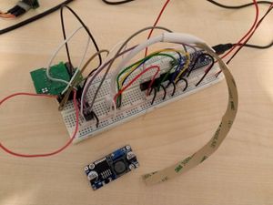
The idea behind this "device" is to create a common software and hardware design, to enable the advanced user to build a custom LED-Dimmer.
Soldering and PCB will be limited to Breadboard, so everyone who knows which side of the soldering iron will get hot can build it.
It will support a range of 1 up to 12 channels using the 16bit timer/pwm of the atmega µControllers.
Depending on the number of channels, it can be built into a REG-Case for central usage or into module case for decentral usage.
It will support CV (constant voltage) LED up to 24V and CC (constant current) LED.
Maybe for some configurations I (or someone else) will design a pcb.
While the current prototype runs on a Mega2560 Board, I plan switiching to SAMD21 on a ItsyBitsyM0 Board with MicroBCU and a PCA9685 I2C PWM Driver.
With this setup 24 channels in a 9TE casing seem to be possible.
